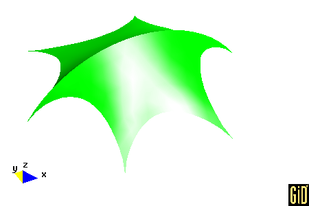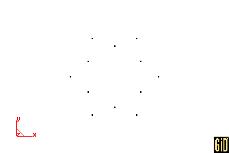
This example was suggested by Katalin Krisztina Klinka, a Civil Enginnering student from Budapest University of Technology and Economics.
Run GiD.
Select Data --> Problem type --> formfind.
Select Geometry --> Create --> Point.
| Point | Coordinates |
| 1 | -5.0, -8.6603, 0.0 |
| 2 | 0.0, -6.9282, 0.0 |
| 3 | 5.0, -8.6603, 0.0 |
| 4 | 6.0, -3.4641, 0.0 |
| 5 | 10.0, 0.0000, 0.0 |
| 6 | 6.0, 3.4641, 0.0 |
| 7 | 5.0, 8.6603, 0.0 |
| 8 | 0.0, 6.9282, 0.0 |
| 9 | -5.0, 8.6603, 0.0 |
| 10 | -6.0, 3.4641, 0.0 |
| 11 | -10.0, 0.0000, 0.0 |
| 12 | -6.0, -3.4641, 0.0 |
At the command prompt, enter the following 12 point coordinates in a single line: -5.0,-8.6603,0.0 0.0,-6.9282,0.0 5.0,-8.6603,0.0 6.0,-3.4641,0.0 10.0,0.0000,0.0 6.0,3.4641,0.0 5.0,8.6603,0.0 0.0,6.9282,0.0 -5.0,8.6603,0.0 -6.0,3.4641,0.0 -10.0,0.0000,0.0 -6.0,-3.4641,0.0
Press ESC to leave point creation.
Select View --> Zoom --> Frame.

Select View --> Label --> All in --> POINT.
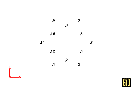
Select Geometry --> Create --> Arc.
Click next to point 1 and click JOIN, click next to point 2 and click JOIN, click next to point 3 and click JOIN. Repeat this procedure for points (3,4,5), (5,6,7), (7,8,9), (9,10,11) and (11,12,1).
Press ESC to leave arc creation.
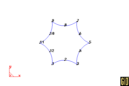
Select Geometry --> Create --> Line.
Click next to point 11 and click JOIN, click next to point 5 and click JOIN. Press ESC to leave line creation.
Press ESC to leave entering points.
Select View --> Label --> Off. Select View --> Label --> All in --> LINE.
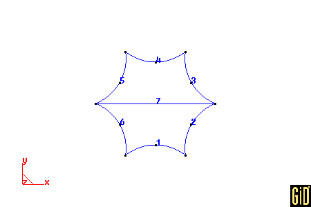
Select Geometry --> Create --> NURBS surface --> By contour.
Click on each of the following lines (1,2,7,6). Press ESC to leave entering lines. Repeat this procedure for lines (4,5,7,3).
Press ESC to leave NURBS surface creation.
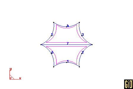
Select Data --> Materials --> Fabric --> Assign --> Surfaces. Then click one of the interior sides for each NURBS surface. Then click Finish. Then click Close.
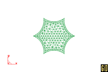
Select Meshing --> Generate. Enter 1.3 for the size of elements. Then click Ok. Then Click Ok.
Select Data --> Conditions --> Displacement.
Assign displacements to points according to the following table. Click Assign, click near the point. Click Finish. After the last point, click Close.
| Point | Displacements |
| 100 | -1.523081, 0.000000, 0.891001 |
| 88 | -1.418223, 0.000000, 2.093213 |
| 82 | -1.305372, 0.000000, 3.132628 |
| 77 | -1.184148, 0.000000, 4.047562 |
| 73 | -1.054194, 0.000000, 4.855675 |
| 72 | -0.915184, 0.000000, 5.564087 |
| 69 | -0.766833, 0.000000, 6.173482 |
| 71 | -0.608907, 0.000000, 6.679972 |
| 76 | -0.441230, 0.000000, 7.075905 |
| 80 | -0.263700, 0.000000, 7.350085 |
| 93 | -0.076296, 0.000000, 7.487515 |
| 107 | 0.116415, 0.000000, 7.470915 |
| 122 | 0.299277, 0.000000, 7.306588 |
| 133 | 0.472262, 0.000000, 7.012986 |
| 145 | 0.635432, 0.000000, 6.604354 |
| 157 | 0.788923, 0.000000, 6.091402 |
| 166 | 0.932938, 0.000000, 5.481519 |
| 179 | 1.067737, 0.000000, 4.778578 |
| 190 | 1.193624, 0.000000, 3.982195 |
| 208 | 1.310942, 0.000000, 3.086084 |
| 227 | 1.420058, 0.000000, 2.074435 |
| 237 | 1.523081, 0.000000, 0.891001 |
| 238 | -1.000000, -1.732051, 0.000000 |
| 249 | 1.000000, -1.732051, 0.000000 |
| 99 | 1.000000, 1.732051, 0.000000 |
| 1 | -1.000000, 1.732051, 0.000000 |
Select File --> Save as. Then select a folder (Directory) and a project name (File name). Click Save.
Important: The input file (input.txt) for the computer code (formfind.exe) will be available in this folder.
Select Calculate --> Calculate. Click OK.
Select Files --> Postprocess.
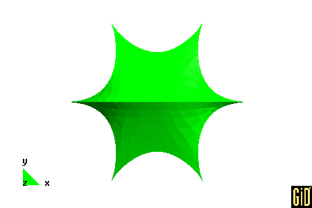
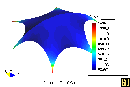
Select View results --> Contour Fill --> Stress 1 (notice that these stresses have no meaning). Select View --> Rotate --> Trackball. Press the left button and drag around the screen.
Select View results --> No results. Select View --> Render --> Smooth lighting.
